BE 2025 Groupe2: Difference between revisions
| Line 50: | Line 50: | ||
En attendant, nous recherchons des librairies pour coder en C. | En attendant, nous recherchons des librairies pour coder en C. | ||
=== Chapitre 3 === | |||
On commence a coder, on a fait du code pour faire du bruit et allumer les leds avec notre petite carte arduino | |||
<nowiki><code></nowiki> | |||
<nowiki>#</nowiki>include <avr/io.h> | |||
<nowiki>#</nowiki>include <util/delay.h> | |||
<nowiki>#</nowiki>define BUZZER_BIT PD3 | |||
// Fonction pour faire un bip à une fréquence spécifique | |||
// delai_us : plus il est petit, plus le son est aigu | |||
void bip_tonalite(uint16_t delai_us, uint16_t duree_boucle) { | |||
for (uint16_t i = 0; i < duree_boucle; i++) { | |||
PORTD &= ~(1 << BUZZER_BIT); // On active le buzzer (LOW) | |||
_delay_us(100); // On triche un peu pour la fréquence | |||
// On utilise une boucle manuelle car _delay_us demande une constante | |||
for(uint16_t d=0; d < delai_us; d++) { _delay_us(1); } | |||
PORTD |= (1 << BUZZER_BIT); // On coupe le buzzer (HIGH) | |||
for(uint16_t d=0; d < delai_us; d++) { _delay_us(1); } | |||
} | |||
} | |||
int main(void) { | |||
// Configuration : LEDs (PB5, PB4, PB3) et Buzzer (PD3) en SORTIE | |||
DDRB |= (1 << PB5) | (1 << PB4) | (1 << PB3); | |||
DDRD |= (1 << BUZZER_BIT); | |||
// Configuration : Boutons (PC1, PC2, PC3) en ENTRÉE avec Pull-up | |||
DDRC &= ~((1 << PC1) | (1 << PC2) | (1 << PC3)); | |||
PORTC |= (1 << PC1) | (1 << PC2) | (1 << PC3); | |||
// Initialisation : Tout éteint (Logique inversée sur ce shield) | |||
PORTB |= (1 << PB5) | (1 << PB4) | (1 << PB3); | |||
PORTD |= (1 << BUZZER_BIT); | |||
uint8_t s1_mem = 0, s2_mem = 0, s3_mem = 0; | |||
while(1) { | |||
// --- BOUTON S1 (LED D1 - Son Grave) --- | |||
if (!(PINC & (1 << PC1))) { | |||
if (!s1_mem) { | |||
PORTB ^= (1 << PB5); | |||
bip_tonalite(800, 50); // Son grave | |||
s1_mem = 1; | |||
} | |||
} else { s1_mem = 0; } | |||
// --- BOUTON S2 (LED D2 - Son Médium) --- | |||
if (!(PINC & (1 << PC2))) { | |||
if (!s2_mem) { | |||
PORTB ^= (1 << PB4); | |||
bip_tonalite(400, 100); // Son médium | |||
s2_mem = 1; | |||
} | |||
} else { s2_mem = 0; } | |||
// --- BOUTON S3 (LED D3 - Son Aigu) --- | |||
if (!(PINC & (1 << PC3))) { | |||
if (!s3_mem) { | |||
PORTB ^= (1 << PB3); | |||
bip_tonalite(150, 200); // Son aigu | |||
s3_mem = 1; | |||
} | |||
} else { s3_mem = 0; } | |||
_delay_ms(10); // Petite pause pour la stabilité | |||
} | |||
} | |||
<nowiki></code></nowiki> | |||
et le makefile | |||
<nowiki><code></nowiki> | |||
export CC = avr-gcc | |||
export LD = avr-gcc | |||
export MCU = atmega328p | |||
export FCPU = 16000000 | |||
export TARGET_ARCH = -mmcu=$(MCU) | |||
export CFLAGS = -Wall -I. -DF_CPU=$(FCPU) -Os | |||
export LDFLAGS = -g $(TARGET_ARCH) -lm -Wl,--gc-sections | |||
TERM = /dev/ttyACM0 | |||
PGMERISP = -c stk500v1 -b 115200 -P $(TERM) | |||
export DUDE = /usr/bin/avrdude -F -v -p $(MCU) | |||
<nowiki>#</nowiki> Le nom sera a changer en fonction du fichier | |||
TARGET = servo | |||
C_SRC = $(wildcard *.c) | |||
OBJS = $(C_SRC:.c=.o) | |||
all: $(TARGET).hex | |||
clean: | |||
rm -f $(OBJS) $(TARGET).hex $(TARGET).elf | |||
$(TARGET).elf: $(OBJS) | |||
$(LD) $(LDFLAGS) -o $@ $(OBJS) | |||
$(TARGET).hex: $(TARGET).elf | |||
avr-objcopy -j .text -j .data -O ihex $(TARGET).elf $(TARGET).hex | |||
upload: $(TARGET).hex | |||
stty -F $(TERM) hupcl | |||
$(DUDE) $(PGMERISP) -U flash:w:$(TARGET).hex | |||
size: $(TARGET).elf | |||
avr-size --format=avr --mcu=$(MCU) $(TARGET).elf | |||
<nowiki></code></nowiki> | |||
Revision as of 15:53, 13 February 2026
Proposition d'objet
On a choisit notre projet, on va faire une carte qui émet du bruit
On a besoin:
- Une carte
- Un émetteur de son
- Une carte SD
- 4 boutons
- 5 leds
- Un lecteur de carte SD
- Une prise jack
Carte électronique
Carte réalisée en utilisant le logiciel KiCAD : File:2025 BE G2 kicad.zip.
Schéma électronique de la carte :

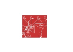
Résultat du routage :

Photo de la carte soudée :
Vidéo très courte et en basse résolution de la carte en fonctionnement :
Travail effectué
Chapitre 1
On a copier coller des choses de différents projets pour avoir une projet avec un lecteur de carte SD, un haut parleur et une prise jack.
Avec ça on a 5 boutons et 4 leds, qui vont nous servir a activer certaines musiques présentes sur la carte SD, et le dernier bouton servira à arrêter la musique.
Chapitre 2
On a terminé de router, on va maintenant imprimer la carte pour ensuite commencer à coder.
Voici le plot pdf.
On a essayer d'installer l'extension JLCPCB mais notre machine est cassé et n'arrive pas a lancer les extensions.
Nous allons donc essayer sur un autre pc a la prochaine séance.
En attendant, nous recherchons des librairies pour coder en C.
Chapitre 3
On commence a coder, on a fait du code pour faire du bruit et allumer les leds avec notre petite carte arduino
<code>
#include <avr/io.h>
#include <util/delay.h>
#define BUZZER_BIT PD3
// Fonction pour faire un bip à une fréquence spécifique
// delai_us : plus il est petit, plus le son est aigu
void bip_tonalite(uint16_t delai_us, uint16_t duree_boucle) {
for (uint16_t i = 0; i < duree_boucle; i++) {
PORTD &= ~(1 << BUZZER_BIT); // On active le buzzer (LOW)
_delay_us(100); // On triche un peu pour la fréquence
// On utilise une boucle manuelle car _delay_us demande une constante
for(uint16_t d=0; d < delai_us; d++) { _delay_us(1); }
PORTD |= (1 << BUZZER_BIT); // On coupe le buzzer (HIGH)
for(uint16_t d=0; d < delai_us; d++) { _delay_us(1); }
}
}
int main(void) {
// Configuration : LEDs (PB5, PB4, PB3) et Buzzer (PD3) en SORTIE
DDRB |= (1 << PB5) | (1 << PB4) | (1 << PB3);
DDRD |= (1 << BUZZER_BIT);
// Configuration : Boutons (PC1, PC2, PC3) en ENTRÉE avec Pull-up
DDRC &= ~((1 << PC1) | (1 << PC2) | (1 << PC3));
PORTC |= (1 << PC1) | (1 << PC2) | (1 << PC3);
// Initialisation : Tout éteint (Logique inversée sur ce shield)
PORTB |= (1 << PB5) | (1 << PB4) | (1 << PB3);
PORTD |= (1 << BUZZER_BIT);
uint8_t s1_mem = 0, s2_mem = 0, s3_mem = 0;
while(1) {
// --- BOUTON S1 (LED D1 - Son Grave) ---
if (!(PINC & (1 << PC1))) {
if (!s1_mem) {
PORTB ^= (1 << PB5);
bip_tonalite(800, 50); // Son grave
s1_mem = 1;
}
} else { s1_mem = 0; }
// --- BOUTON S2 (LED D2 - Son Médium) ---
if (!(PINC & (1 << PC2))) {
if (!s2_mem) {
PORTB ^= (1 << PB4);
bip_tonalite(400, 100); // Son médium
s2_mem = 1;
}
} else { s2_mem = 0; }
// --- BOUTON S3 (LED D3 - Son Aigu) ---
if (!(PINC & (1 << PC3))) {
if (!s3_mem) {
PORTB ^= (1 << PB3);
bip_tonalite(150, 200); // Son aigu
s3_mem = 1;
}
} else { s3_mem = 0; }
_delay_ms(10); // Petite pause pour la stabilité
}
}
</code>
et le makefile
<code>
export CC = avr-gcc
export LD = avr-gcc
export MCU = atmega328p
export FCPU = 16000000
export TARGET_ARCH = -mmcu=$(MCU)
export CFLAGS = -Wall -I. -DF_CPU=$(FCPU) -Os
export LDFLAGS = -g $(TARGET_ARCH) -lm -Wl,--gc-sections
TERM = /dev/ttyACM0
PGMERISP = -c stk500v1 -b 115200 -P $(TERM)
export DUDE = /usr/bin/avrdude -F -v -p $(MCU)
# Le nom sera a changer en fonction du fichier
TARGET = servo
C_SRC = $(wildcard *.c)
OBJS = $(C_SRC:.c=.o)
all: $(TARGET).hex
clean:
rm -f $(OBJS) $(TARGET).hex $(TARGET).elf
$(TARGET).elf: $(OBJS)
$(LD) $(LDFLAGS) -o $@ $(OBJS)
$(TARGET).hex: $(TARGET).elf
avr-objcopy -j .text -j .data -O ihex $(TARGET).elf $(TARGET).hex
upload: $(TARGET).hex
stty -F $(TERM) hupcl
$(DUDE) $(PGMERISP) -U flash:w:$(TARGET).hex
size: $(TARGET).elf
avr-size --format=avr --mcu=$(MCU) $(TARGET).elf
</code>